York RTU Airflow Noise Fix
York RTU Airflow Noise Fix
Is your York RTU creating loud airflow noise? Learn how to reduce fan speed safely using CLS % settings—without damaging the system or freezing the coil.
🧭 Customer Issue: Excessive Airflow Noise in a Small Office
On a routine service call to a single-story commercial building, the complaint wasn't about insufficient cooling. Instead, the occupants reported that the airflow from their ceiling vents was too strong—causing constant noise that disrupted conversations and daily work. The space was reaching the desired temperature, but the sound of air rushing from the diffusers had become a source of discomfort.
The building was equipped with a York rooftop unit (RTU). According to the customer, all zone dampers were fully open, and no visible obstructions were found in the ductwork. With only one floor, static pressure losses were expected to be minimal. Despite this, the airflow at each supply register was intense and noisy.
From the customer’s perspective, the request was straightforward: reduce the noise. However, as HVAC technicians, we know that modifying airflow affects more than just acoustics. It can influence system efficiency, temperature balance, and even equipment lifespan. To resolve the issue effectively, the goal was to reduce perceived airflow without compromising the system’s designed performance.
🔍 Initial Inspection: VFD Not Active
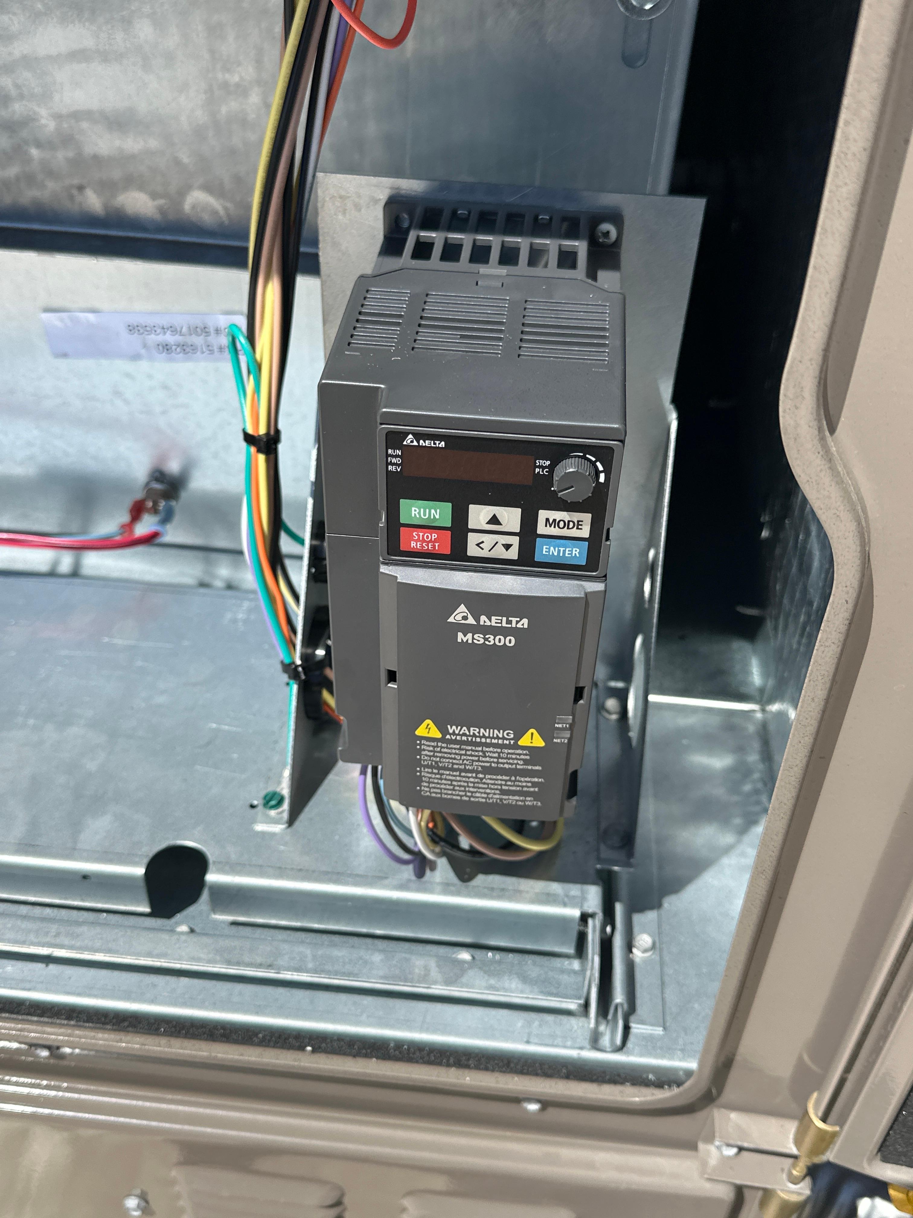
Upon opening the blower compartment of the rooftop unit, I located what appeared to be a Delta MS300 variable frequency drive (VFD) installed near the motor. Typically, when excessive airflow is reported, adjusting the VFD can be a direct way to reduce fan speed. However, in this case, the drive's display was only faintly blinking—there was no frequency output, no signs of motor modulation, and no indication that the VFD was actively managing blower operation.
This observation suggested that the unit was not utilizing the VFD, even though one was physically installed. The reason for this was unclear—it may not have been programmed, or it might have been disabled through the control system settings.
Given the lack of activity from the VFD, the next logical step was to access the unit's onboard controller. York RTUs equipped with Smart Equipment™ controls can often manage airflow parameters internally. By shifting focus from the VFD hardware to the control logic, it became possible to explore whether the unit was operating in a fixed-speed mode and if any airflow adjustments could be made directly through the controller interface.
🛠️ Adjusting Fan Settings Through York’s Smart Equipment™ Controller
To explore software-level adjustments, I accessed the Smart Equipment™ control interface built into the York rooftop unit. This onboard system features an integrated LED screen with navigation buttons, allowing direct configuration of multiple system parameters, including fan operation and compressor staging.
Based on prior guidance from York technical support, I searched for airflow settings that correspond to compressor activity. The recommended method was to adjust the Cooling Stage CLS Percent values—settings that determine the blower speed relative to each active stage of cooling demand.
Using the interface, I navigated:
Menu → Fan Settings → Cooling Stage CLS%
I configured the system to operate the indoor fan at 60% speed during the 1st cooling stage and 90% during the 2nd stage. These adjustments do not affect the blower's total CFM or its mechanical configuration. Instead, they enable the unit to modulate airflow dynamically depending on load conditions—reducing airflow during partial load without altering physical components.
York's technical team specifically advised against modifying total airflow mechanically unless the system was fully re-evaluated. Lowering CFM beyond design limits can lead to reduced coil performance, increased risk of freezing, and uneven dehumidification. In contrast, adjusting fan speed by stage using built-in controls offers a balanced and manufacturer-supported solution that addresses comfort issues without compromising equipment reliability.
⚙️ Solution Approach: Modulating Fan Speed by Cooling Stage
Instead of reducing the total system airflow—which can disrupt the designed refrigerant-air balance and risk coil freezing—a more controlled method involves adjusting the fan speed for each cooling stage using the built-in Smart Equipment™ controller. This approach preserves full-load airflow performance while reducing fan intensity during lighter cooling demands.
For this service case, the 1st stage Cooling Load Share (CLS) % was set to 60%, allowing the blower to run at 60% of its rated capacity when only one compressor is active. This adjustment helped decrease the noise and velocity of air at the supply diffusers without negatively impacting occupant comfort.
The 2nd stage CLS % was set to 90%, reserving near-full airflow for high-load conditions when both compressors are engaged. Since many commercial buildings operate in partial-load mode during large portions of the day, especially under mild ambient conditions, this stage-based fan control allowed the system to run more quietly while maintaining cooling efficiency.
These CLS % values serve as digital setpoints for the indoor fan speed relative to its maximum output. They do not involve mechanical changes such as altering pulleys or belts. Instead, they instruct the system’s VFD or internal logic to regulate fan speed based on current demand, aligning airflow output more closely with thermal load.
By using this built-in feature, the unit continues operating within manufacturer specifications while enhancing acoustic comfort—a practical solution that supports both equipment longevity and user satisfaction.
🚫 Why Reducing Total CFM Can Be Risky
When addressing airflow noise issues, it may seem reasonable to lower total system airflow by adjusting the blower pulley or reducing fan speed. However, with YORK rooftop units—as well as many other packaged systems—this approach can lead to operational problems and even long-term equipment damage.
These systems are engineered to maintain a specific balance between airflow volume (CFM), refrigerant charge, and coil design. Reducing the CFM below factory specifications can disrupt this balance and cause several issues:
- Evaporator coil freezing: Insufficient airflow prevents proper heat absorption, causing the coil to drop below freezing temperatures and potentially ice over.
- Reduced dehumidification: Lower airflow alters the balance between latent and sensible heat, making it more difficult for the system to control indoor humidity effectively.
- Compressor stress: Poor heat exchange can result in elevated suction pressures and inadequate oil return, both of which reduce the compressor’s service life.
- Uneven temperature distribution: In larger or multi-room setups, decreasing airflow can lead to inconsistent cooling, especially in areas furthest from the supply fan.
YORK equipment is rated and certified based on carefully tested airflow conditions. The factory-calibrated CFM levels are directly tied to the unit’s cooling capacity (as per AHRI standards) and SEER performance. Adjusting airflow outside these parameters compromises the system’s efficiency, reliability, and certification.
For this reason, YORK technical guidance recommends maintaining total design airflow and instead using control-based methods—such as stage-specific fan speed adjustments (CLS %)—to manage comfort and reduce noise during partial load operation.
This method ensures safe operation, maintains system performance, and avoids unintended consequences that can arise from altering airflow mechanically.
✅ Final Result: Reduced Noise Without Sacrificing Performance
After updating the fan speed settings using the York Smart Equipment™ controller—60% for first-stage cooling and 90% for second-stage—the unit quickly adapted to the new parameters. During partial-load operation, the blower speed decreased noticeably, and the excessive airflow noise reported by the occupants was no longer present.
To verify the results, I walked through each zone with the client. The rooms remained comfortably cool, but the high-velocity sound from the vents had been significantly reduced. Normal conversation was no longer disrupted by airflow, and the client remarked that the space felt noticeably more pleasant and quieter.
Crucially, system performance remained stable. Because the total CFM was not altered through mechanical means, airflow across the evaporator coil stayed within the manufacturer’s intended range. This ensured the unit continued to operate without the risk of coil freezing or uneven cooling.
This case illustrates how a small control adjustment can provide measurable improvement without changing any hardware. Understanding how to modify settings based on cooling stages allowed us to resolve a noise issue while maintaining system efficiency and reliability.
Before completing the service call, I documented the updated values, verified that all panels were secure, and explained the changes to the customer. The resolution was simple but effective—an example of how practical system knowledge and proper use of built-in features can address occupant comfort concerns efficiently.
📌 Practical Tip: Safely Reducing Airflow in a York RTU
When working with a York rooftop unit that produces excessive airflow—often leading to noise complaints or excessive throw at diffusers—it is important to take a methodical approach. Adjusting fan speed without considering system design may lead to performance issues or long-term damage.
Here is a recommended step-by-step procedure for addressing airflow using the Smart Equipment™ control interface:
1. Verify the VFD Status (if applicable):
Check whether a variable frequency drive (VFD) is installed and functioning. If present but inactive, airflow modulation may not occur, even if the system supports it.
2. Navigate to the Smart Equipment™ Interface:
Use the LED screen and built-in navigation controls to reach:
Menu → Fan Settings → Cooling Stage CLS %
3. Set CLS % Values by Cooling Stage:
Instead of altering total airflow, adjust fan output for each cooling stage:
- 1st Stage CLS %: 60%
- 2nd Stage CLS %: 90%
This method helps reduce noise during low-demand conditions while preserving full airflow during peak loads.
4. Avoid Mechanical Adjustments Without Engineering Review:
Modifying pulleys or belts can affect refrigerant flow, lead to coil freezing, or damage the compressor. These changes should only be made with system re-design.
5. Monitor System Behavior Post-Adjustment:
Observe system pressures, sound levels, and space temperatures to ensure stable operation. Verify that no short cycling or coil performance issues occur.
By following this approach, technicians can reduce noise and enhance comfort without compromising system integrity. The key is to work within manufacturer guidelines and use available control features strategically.
✅ Conclusion
Effective HVAC service often requires more than mechanical changes—it involves understanding the built-in logic and capabilities of the equipment. In this case, a minor adjustment through the York Smart Equipment™ controller significantly improved acoustic comfort while maintaining reliable system performance.
Addressing issues like airflow noise doesn’t always demand hardware replacement. When approached correctly, small changes in control settings can make a noticeable difference. Prioritizing system design and using manufacturer-supported solutions is essential to delivering both comfort and long-term reliability.
👉 Want to read this in Korean? 클릭하세요