1.1 Electronic Thermostats and Temperature Controls: Electronic Thermostats
Electrical resistance is the force that opposes the flow of electrical current. A thermistor operates using a ceramic semiconductor whose electrical resistance changes as temperature changes. This predictable behavior allows thermistors to be used for temperature sensing in HVAC systems.
There are two primary types of thermistors:

- PTC (Positive Temperature Coefficient)
Resistance increases as temperature rises and decreases as temperature falls. PTC thermistors are not commonly used for thermostat temperature sensing but are typically applied in motor control circuits. - NTC (Negative Temperature Coefficient)
NTC thermistors are widely used in HVAC controls. They have an inverse relationship between temperature and resistance—when temperature increases, resistance decreases. These devices are used to measure air temperature in ductwork and fluid temperature when surface-mounted on piping.
Electronic Thermostats and Low-Voltage Design
Electronic thermostats used in heating and cooling systems generally operate at 24 volts, which is considered low voltage and safer than high-voltage systems. Rather than switching power directly, these thermostats rely on relays or electronic switches to control HVAC equipment.
Thermostat Wiring Overview
Thermostat control wiring consists of multiple color-coded conductors. Each wire is labeled on both the thermostat sub-base and the furnace or air handler terminal strip.
The most common control wires include:


- R (Red) – Supplies 24-volt power from the transformer to the thermostat
- W (White) – Controls heating operation
- Y (Yellow) – Controls the compressor contactor
- G (Green) – Controls the indoor blower relay
All electronic thermostats also require a common wire (C) to complete the electrical circuit.
- The common wire provides the return path for current back to the transformer
- In most systems, the blue wire is used as the common
- It is connected to the transformer secondary common terminal or the C terminal on the furnace or air handler
Heating and Cooling Operation
In heating mode, when the room temperature falls below the programmed set point, the heating contacts within the thermostat close and energize the heating system. The set point is programmed by the homeowner or technician.
In cooling mode, when the room temperature rises above the set point, the cooling contacts close. This action also allows the fan relay to be energized, enabling airflow through the system.
Selecting an Electronic Thermostat
Choosing an electronic thermostat requires balancing form, function, and price, while ensuring accurate temperature control. One of the most important features to consider is temperature setbacks.
- Setbacks automatically adjust heating and cooling set points based on occupancy
- They save energy by allowing temperature drift when the space is unoccupied
- Comfort is restored when occupants return
Many programmable thermostats also include a recovery feature that starts heating or cooling before a scheduled period begins, ensuring the desired temperature is reached on time. While schedules can be customized, most thermostats include default programs designed around typical daily routines.
Smart Thermostats and Remote Access
Modern thermostats often include remote access capabilities through Wi-Fi or Bluetooth connections.
- Allows thermostat control from anywhere using a smart device
- Enables users to override programmed temperature settings
- Takes advantage of existing home internet connections
Electromechanical Thermostats
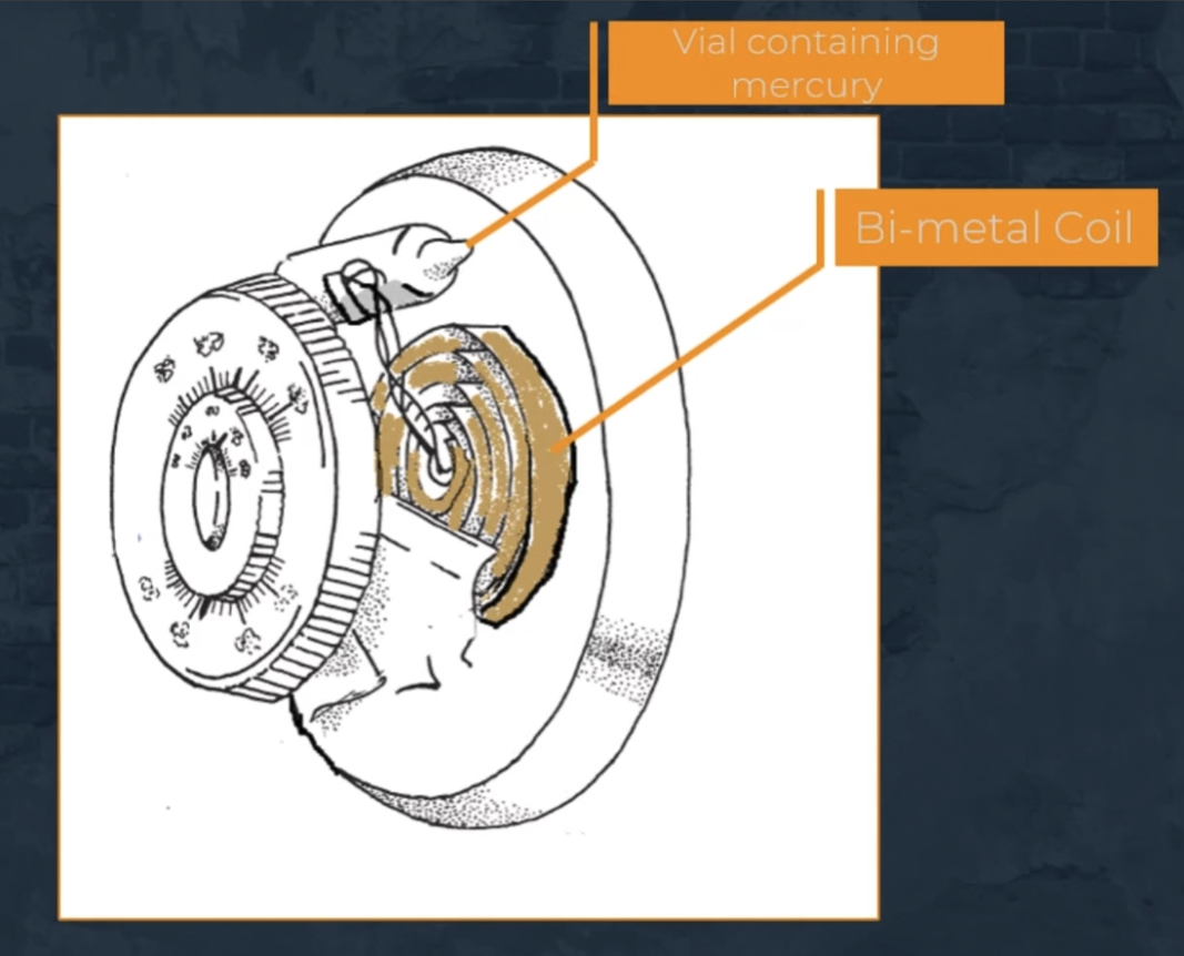
Although less common today, electromechanical thermostats may still be found in the field. These non-programmable devices use a bimetal coil or strip that moves in response to room temperature changes, opening and closing electrical contacts to control HVAC equipment.
Some older electromechanical thermostats contain mercury, which is a hazardous material and is no longer manufactured in the United States. In these thermostats, temperature changes cause a mercury-filled vial to tilt.
- Mercury flows to one end of the vial
- Electrical contacts are completed
- Voltage from the R terminal is sent to the heating, cooling, or fan relay
Manual switches on these devices determine heating or cooling mode, while an Auto/On fan switch controls whether the blower runs continuously for ventilation or only during a call for cooling.
1.2 Electronic Thermostats and Temperature Controls: Temperature Controls
Low Ambient Controls and Head Pressure

Head pressure is the pressure generated by the compressor in an air conditioning system. When outdoor temperatures drop, head pressure can also decrease, which can negatively affect system operation. To prevent this, low ambient controls are used to maintain a minimum head pressure during low outdoor temperature conditions.
The most common low ambient control used in refrigeration systems is the fan cycling control. These controls are pressure switches that may be factory-set and non-adjustable or adjustable by a technician or installer.
The operation of a fan cycling low ambient control follows a simple pressure-based sequence:
- When head pressure drops to the cut-out set point, the control switch opens
- The condenser fan shuts off, allowing head pressure to rise
- When head pressure reaches the cut-in point, the control switch closes
- The condenser fan restarts
Maintaining minimum head pressure is essential because it ensures a proper pressure drop across the metering device and allows correct liquid refrigerant metering into the evaporator. Some systems achieve this control by using multi-speed condenser fans, which adjust fan speed based on outdoor temperature instead of cycling the fan on and off.
Bimetal Temperature Controls

Bimetal temperature controls operate using two dissimilar metals fused together along their entire length. Because the two metals expand at different rates when heated, the strip bends or curves as temperature changes.
These controls are commonly used as high-limit temperature switches in furnaces. The bending action of the bimetal allows the control to make or break electrical contacts, thereby controlling electrical current flow.
One important limitation of bimetal temperature controls is their limited service life. Due to this limitation, it is important to verify their proper operation on an annual basis to ensure safe and reliable furnace operation.
Electronic Fossil Fuel Backups (Dual Fuel / Hybrid Systems)
Electronic fossil fuel backups, also known as dual fuel or hybrid systems, are designed to operate using multiple energy sources. These systems are used when a standard HVAC system alone cannot meet heating demand, particularly during very cold conditions.
A common example of a hybrid system is a heat pump combined with a fossil fuel furnace. In this arrangement, the furnace provides auxiliary or supplemental heat when the heat pump becomes ineffective.
In a typical ducted HVAC system, an air handler is used to move conditioned air through the ductwork. In a dual fuel system, however:
- The air handler is replaced by a furnace
- The furnace provides fossil fuel heat instead of electric heat
- The furnace and heat pump must never operate at the same time
Auxiliary Heat Staging and Balance Point
The operation of a dual fuel system relies on staging, which is the process of defining specific conditions and programming the system to respond accordingly.
The staging sequence generally follows this order:
- First stage: Heat pump heating (compressor operation)
- Second stage: Furnace heating
The transition between these stages is based on the balance point, which is the lowest outdoor temperature at which the heat pump can meet the building’s heating demand without assistance.
Key points about the balance point:
- Typically occurs around 40°F
- When outdoor temperature reaches the balance point:
- The heat pump is cycled off
- The furnace is cycled on
- This transition is controlled by the fossil fuel backup system
Role of the Fossil Fuel Backup Control
If the thermostat used in a dual fuel system does not have the capability to manage heat pump and furnace staging, a fossil fuel backup control is installed.
This control system:
- Receives input signals from outdoor temperature sensors
- May also use sensors located inside the conditioned space
- Processes these inputs to determine which heating source should operate
- Sends the correct output signals to either the heat pump or the furnace
By managing these inputs and outputs, the fossil fuel backup ensures proper system operation, efficiency, and equipment protection.
2. Safety Controls
Disk-Type Temperature Limit Controls
Disk-type temperature limit controls operate in a manner similar to bimetal controls. They are small, button-shaped devices typically embedded in the plenum or heat exchanger area of a furnace.
Their primary function is to monitor air temperature and act as a high-limit safety device. If the temperature exceeds the preset limit, the control shuts down the furnace to prevent overheating. This type of control is commonly found in older furnace systems.
In some furnaces, a second disk-type device is installed near the limit control. This secondary device is used to activate the blower fan when the temperature around the heat exchanger rises to a certain level.
Disk-Type High and Low Pressure Controls

Disk-type high and low pressure controls operate using an internal diaphragm. The diaphragm deflects in response to system pressure, causing electrical contacts to open or close at specific set points.
High Pressure Safety Controls
A high pressure safety control opens its switch contacts when system pressure rises above the maximum allowable limit. This condition often occurs when heat is not being properly rejected.
- A common example is a dirty condenser coil in an air conditioning unit
- Restricted airflow causes pressure to rise
- The high pressure switch opens and shuts off the compressor to prevent damage
Low Pressure Safety Controls
A low pressure safety control opens its contacts when system pressure drops below a preset level.
- One cause is loss of refrigerant, which lowers system pressure
- When this occurs, the control shuts off the compressor to protect it
In heat pump systems, excessive frost buildup on the outdoor coil can also cause refrigerant pressure to drop. In these cases:
- A low pressure switch senses the pressure drop
- The switch initiates the defrost cycle on certain heat pump systems
Vapor Charged Controls

Vapor charged controls use a sensing bulb filled with gas. As temperature changes:
- The gas expands and contracts
- This movement opens or closes electrical switch contacts
These controls respond directly to temperature changes through gas pressure rather than mechanical bending or electrical sensing.
Motor Overload Controls

Motor overloads are safety controls designed to protect motors from overheating and excessive current draw. They monitor:
- Motor temperature
- Motor electrical current
When unsafe conditions are detected, the overload control opens the circuit and breaks power to the motor, shutting it down to prevent damage.
Fuses and Fusible Links
A fuse is an electrical safety device that provides overcurrent protection for an electrical circuit. In HVAC systems, fuses are commonly used to protect:
- Compressors
- Evaporator coils
- Motors
- Electrical wiring
Fuses and fusible links are designed to break the electrical circuit when current exceeds the circuit’s designed limit. This reaction is intentional and severe.
Important characteristics of fuses and fusible links:
- Once they open, they cannot be reset
- They must be replaced after operation
- They are specified by:
- Voltage rating
- Amperage rating
- Physical size (most critical)
The physical size of a fuse is directly related to its amperage rating. When replacing a fuse, it must exactly match the original specification installed in the system.
3. Zone Controls
Purpose and Benefits of Zoning

Installing a zoning system allows a homeowner to heat or cool specific rooms or sections of the home independently. This makes it possible to maintain a desired comfort level in one area without affecting surrounding spaces.
Zoning considerations should be identified during the technician’s initial heating load analysis, because different areas of a home often have different heating and cooling requirements. These differences are driven by several heat load factors, including:
- Sun movement throughout the day
- Airflow patterns within the home
- Occupancy levels in different rooms
Because of these variables, zone placement must be carefully planned to match the actual usage and thermal behavior of the home.
Cost and Energy Considerations
While zoning systems can help save energy and reduce utility costs, those savings must be weighed against the higher installation cost of a zoning system.
Installation costs can increase based on:
- The number of zones required
- The amount of ductwork modification needed
- Whether existing HVAC components must be replaced or upgraded
Zoning systems can be installed in almost any residence, but they tend to be most effective in multi-story homes. In these homes, upper levels are often too warm while lower levels are too cool, making zoning a practical solution.
Zoning also provides the greatest benefit when addressing challenging architectural features such as:
- Vaulted or high ceilings
- Finished attics or basements
- Large rooms
- Large or numerous windows
- Rooms that are rarely used
How HVAC Zoning Systems Operate
An HVAC zoning system uses multiple thermostats, each assigned to a specific zone within the home. These thermostats communicate with a central zoning control panel, which manages airflow distribution.
Airflow is controlled using motorized dampers, which are installed inside the ductwork. These dampers function like adjustable shutters:
- They open to allow airflow into zones that need heating or cooling
- They close to restrict airflow to zones that do not
This operation is similar to a traffic control system, directing air only where it is needed and preventing wasted airflow.
The number and placement of dampers depend on:
- The ductwork layout
- The zone layout of the home
Static Pressure Considerations
As dampers open and close, certain duct paths become restricted, which affects static pressure within the duct system.
Static pressure is the resistance the blower fan in a furnace or air handler must overcome to move air through the ductwork. It is critical that static pressure remains balanced and within design limits.
Key points about static pressure in zoning systems:
- Closing ducts increases static pressure
- Static pressure must be evenly distributed throughout the system
- Improper zoning design can lead to excessive pressure, reducing system efficiency and potentially damaging equipment
Because of this, zoning systems must be carefully designed to manage airflow changes without overloading the HVAC system.
4.1 Electronic Timers and Defrost Controls: Electronic Timers
What Is an Electronic Timer?
An electronic timer in an HVAC system is a control device that can be programmed to activate or deactivate system components based on time or operating conditions. By limiting equipment operation to periods of building occupancy, electronic timers can significantly improve energy efficiency.
In addition to basic on/off scheduling, timers are often used to delay the opening or closing of relay contacts when voltage is applied to or removed from a control coil. This function is achieved using a time delay relay.
Time Delay Relays and Fan Delay Controls
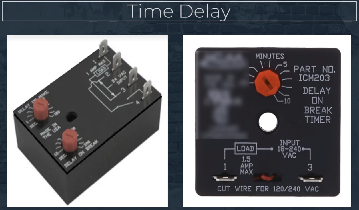
A time delay relay allows contacts to open or close after a preset delay rather than immediately. One common example is a fan delay with a delay on break, where the fan continues running for a set period after power is removed.
Time delay devices may be:
- Fixed-time devices
- Adjustable devices with multiple timing ranges and functions
These time delay features can be built directly into the electronic control board of a furnace or air conditioning system, or they may exist as standalone components.
When integrated into the control board:
- Delay times can often be field-adjusted
- Delay duration can be shortened or lengthened as needed
- The fan control relay is frequently integrated as well
This integration allows the time delay function to work directly with the relay’s external circuitry.
Fan and Blower Delay Applications
Time delays are widely used in furnace and air handler controls to manage blower operation more effectively.
Common applications include:
- Delaying blower startup until the heat exchanger is sufficiently warm
- Allowing the blower to continue running for a set time after a heating or cooling cycle ends
These delays improve comfort and efficiency by maximizing heat transfer and reducing wasted energy.
Compressor Delay Timers and Short Cycling Prevention
Compressor delay timers are especially important for protecting compressors. Their primary purpose is to prevent short cycling, which occurs when a compressor starts and stops too frequently.
Short cycling can cause excessive wear on the compressor motor due to rapid restarting during cooling operation. For this reason:
- Once a compressor shuts down, it must remain off for a minimum time period
- Restarting before this delay expires can damage the compressor
In many systems, the compressor delay function is built directly into the electronic space thermostat, eliminating the need for a separate timer.
Electronic Compressor Controls and Staging
Electronic compressor controls often use a staging strategy. Staging involves identifying predetermined conditions and programming the system to respond appropriately to changing load demands.
Compressor staging is commonly used in systems with multiple compressors. In these systems:
- Compressors are brought on or shut down based on system load
- Multiple compressors are prevented from starting simultaneously
- System efficiency and electrical demand are improved
Control Board Inputs, Outputs, and Monitoring
For electronic control systems to operate correctly, the control board must receive proper inputs and generate the correct outputs. Correct input-to-output response indicates that the control board is functioning properly.
Typical control board inputs include:
- A power supply
- Control signals from thermostats or other controls
In addition, the control board continuously monitors safety devices and control inputs to ensure safe and reliable system operation.
Because electronic controls can vary by manufacturer and application, technicians should always consult the service manual specific to the control being serviced to verify correct inputs, outputs, and operating sequences.
4.2 Electronic Timers and Defrost Controls: Heat Pump Defrost Controls
Defrost Control Boards in Modern Heat Pumps
Modern heat pumps use an electronic defrost control board. This board integrates both a timer and a defrost relay, allowing the system to manage defrost cycles automatically. However, the heat pump will only enter defrost mode if frost is detected on the outdoor coil by the defrost thermostat.
During a defrost cycle while the heat pump is operating in heating mode, several system changes occur:
- The reversing valve shifts position, routing hot discharge gas from the compressor to the outdoor coil
- The outdoor fan shuts off
- The electric heater is energized to provide tempered air to the space
The defrost cycle continues until the defrost thermostat senses approximately 50–60°F on the outdoor coil. At that point, the defrost cycle is terminated and normal heating operation resumes.
The defrost control board also allows a technician to manually initiate a defrost cycle, which is useful for verifying proper system operation during service or troubleshooting. Older heat pumps may use electromechanical timers and relays instead of an integrated electronic control board.
Types of Defrost Control Strategies
Defrost controls can be categorized based on how defrost is initiated and terminated.
Time-Initiated / Time-Terminated (Straight Time)
These defrost controls are regulated strictly by time. If the heat pump operates in heating mode for a preset duration, the system will enter defrost mode regardless of how much frost is actually present on the outdoor coil.
Temperature-Differentiated Controls
The term temperature differentiated refers to any control that uses temperature sensing to indicate a need for defrost rather than relying solely on elapsed time.
Time-Initiated, Temperature-Terminated
These controls initiate defrost based on elapsed time but terminate defrost based on outdoor coil surface temperature. While similar to straight-time controls, they provide better control by ending defrost once the frost has melted and the coil temperature reaches the termination set point.
Time and Temperature-Initiated, Temperature-Terminated
This type of control uses both time and temperature conditions to initiate defrost. The system will not enter defrost mode unless frost is sensed on the outdoor coil. Once defrost begins, the cycle is terminated when the frost has melted and the coil temperature rises to the termination setting.
Metering Devices in HVAC Systems
A metering device is a major component of a refrigeration system. It serves as the dividing point between the high-pressure and low-pressure sides of the system and regulates refrigerant flow into the evaporator based on system demand.
Thermostatic Expansion Valve (TXV)
The most common metering device is the thermostatic expansion valve (TXV), also known as a TV.
- Uses a sensing bulb mounted on the suction line at the evaporator outlet
- Measures evaporator pressure within the valve body
- Opens and closes to regulate refrigerant flow into the evaporator
- Maintains proper superheat
- Often field adjustable
Electronic Expansion Valve (EEV)
Another type of metering device is the electronic expansion valve (EEV).
- Uses a step motor
- Receives input from:
- An NTC thermistor
- A pressure transducer
- Provides very precise control of refrigerant flow to meet evaporator demand
Reversing Valves in Heat Pumps
A reversing valve is a flow control device that determines whether hot discharge gas is routed to the indoor coil or outdoor coil in a heat pump. The reversing valve is typically controlled by the thermostat.
Reversing valves have four pipe connections:
- Discharge inlet (permanent discharge port) – always receives discharge gas from the compressor
- Suction outlet (permanent suction port) – always receives suction vapor returning to the compressor
- Two directional ports – change function based on operating mode
In cooling mode, discharge gas enters the permanent discharge port and is routed to the outdoor coil. In heating mode, discharge gas enters the same port but is routed instead to the indoor coil.
Auxiliary Heat Relays and Staging
The final control covered is the auxiliary heat relay. A relay allows a low-voltage control device, such as a thermostat, to control a high-voltage component, such as an electric heater.
Auxiliary heat operation is tied to staging strategies. Second-stage heat is energized when outdoor temperatures drop and the heat pump alone can no longer keep up with the building’s heat loss. At that point, auxiliary heat provides additional heating capacity to maintain indoor comfort.
'HVAC Fundamental (English) > Fundamental Full' 카테고리의 다른 글
| Introduction to Refrigeration Systems (Full Ver.) (0) | 2026.01.02 |
|---|---|
| Temperature, Pressure, and Heat (Full ver.) (1) | 2025.12.29 |
| Understanding ACCA Standards (Full Ver.) (0) | 2025.12.26 |
| Leak Check and Evacuation (Full Ver.) (0) | 2025.12.26 |
| A2L Refrigerants Introduction (Full Ver.) (0) | 2025.12.22 |