1. Blueprint
Introduction to Blueprints
A blueprint is a technical drawing that serves as a physical map of a building. It details where everything is located and specifies the materials required for construction.
- Synonyms: Floor plan, Reflected Ceiling Plan (RCP).
- Scope: Includes plumbing, electrical layouts, framing, windows, doors, rooms, and appliances.
The Electrician’s Perspective
Electricians use blueprints to understand the physical layout and material requirements of a project. These plans are used across two main fields:
- Architectural: Building structures in residential, commercial, and industrial settings.
- Engineering: Large-scale infrastructure like roads, bridges, and airport runway lighting.
Key Features of Blueprint Sets
Blueprints rarely come as a single page; they are delivered in comprehensive sets.
- Organization: Pages are divided by construction trade (e.g., Electrical, Plumbing) and are typically labeled with letters for easy identification.
- Scale: Since buildings are too large to draw at full size, blueprints are "scaled down."
- Ratio Scale: A scale of 1:50 means the actual building is 50 times larger than the drawing.
- Imperial Scale: Found in the Title Block. For example, a 1/4" scale means 1/4 inch on paper equals 1 foot in reality (a ratio of 1:48).
Symbols and Legends
Drawing realistic components is too time-consuming, so standardized symbols are used to communicate information quickly.

- Common Electrical Symbols:
- Receptacles (outlets)
- Switches (Single-pole, 3-way)
- Lamp holders
- Major appliances (Range, Dryer)
- The Legend: This is the "dictionary" for the blueprint. It defines what every symbol means and is usually located on the first sheet of the electrical drawings.
- Notes: These provide specific, additional instructions or details that cannot be captured by symbols alone.
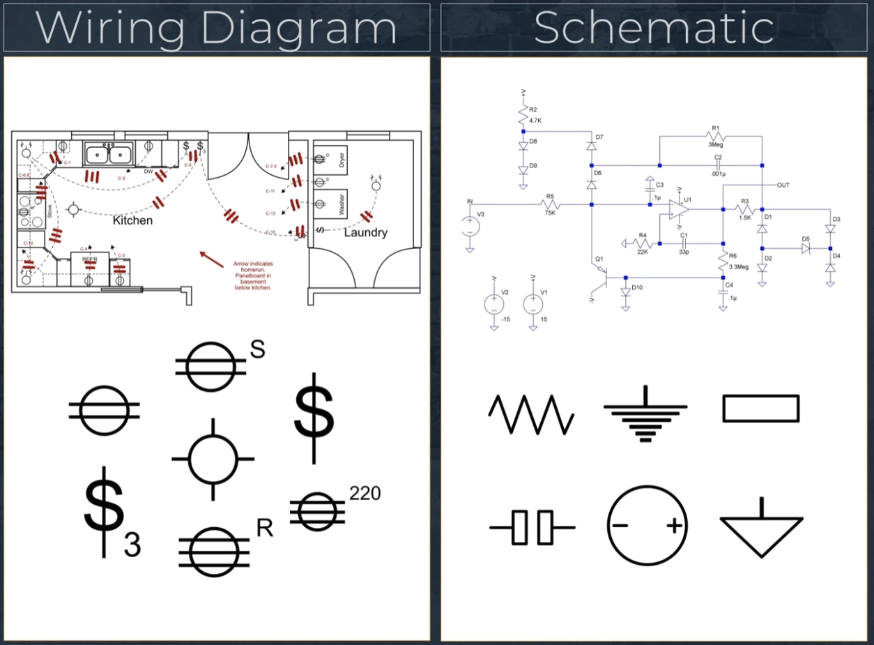
2. Wiring Diagram
What is a Wiring Diagram?
A wiring diagram is a simplified pictorial representation of an electrical system. Unlike a complex schematic, it focuses on the physical location of components and how they are connected.
- Key Function: Shows where components live in a space and the representation of the connections between them.
- Context: These diagrams are part of the electrical plans found within a larger set of blueprints.
The Electrician's Use Case
Electricians rely on these diagrams to plan the physical installation of a system.
- Placement: Used to identify the exact spots for lights, switches, and appliances.
- Routing: Helps determine where cables and conduits will run.
- Circuit Logic: Shows how each component connects back to the circuit breaker.
Reading the Diagram
To interpret a wiring diagram correctly, you must understand the visual language used:
- Symbols: These represent components (like burners on a stove or outlets in a room).
- Note: Symbols can vary between different sets of plans. Always check the legend on the first electrical floor plan page.
- Balloons: These icons indicate the specific placement of outlets or fixtures.
- Connecting Lines: These lines show which components are grouped together on a circuit.
- Letter Labels: Lines are often labeled with letters to indicate which specific breaker in the panel they lead back to.
⚠️ Important Warning
The lines on a wiring diagram indicate electrical relationships, not the literal path of the wire. If an electrician installed wires exactly as drawn (straight lines from point A to point B), the wires would be exposed across floors and ceilings. The lines tell you what to connect, not how to route the physical wire through the walls.
Comparison: Physical vs. Functional
While wiring diagrams are excellent for showing physical location, they are limited. They focus on where things sit in a structure rather than the deep internal logic of the components themselves.
3. Schematics
What is a Schematic?
A schematic is a detailed representation of an electrical circuit's logic. Rather than focusing on where a component is physically located, it focuses on the path of the electrical current.
- Core Elements: Every schematic includes the source (power), conductors (wires), and the load (the device using power).
- Purpose: It shows exactly how electricity travels through a system, making it the primary tool for troubleshooting complex appliances and systems.
Schematic vs. Wiring Diagram
It is crucial to understand the difference between these two types of drawings:
| Feature | Wiring Diagram | Schematic |
| Focus | Physical location and general connection. | The logical path of electrical current. |
| Symbols | Found in the blueprint legend. | Standardized; not usually in the blueprint legend. |
| Goal | Shows where to install components. | Shows how the circuit functions. |
Types of Circuits
Schematics illustrate how components are wired together in three primary configurations:
- Series Circuit: There is only one path for the electrons to flow. If one component fails, the entire circuit is broken.
- Parallel Circuit: Features multiple branches wired in parallel. Electricity can flow through different paths simultaneously.
- Combination Circuit: Contains a mix of both series and parallel components.
Common Schematic Symbols
Unlike architectural symbols, schematic symbols represent the electrical nature of the component. Common symbols include:
- AC (Alternating Current) and DC (Direct Current)
- Positive (+) and Negative (-) wires
- Resistors: Components that resist the flow of current.
- Coils: Often found in motors or transformers.
- Light Bulbs: The load converted into light.
Troubleshooting
When an appliance breaks, technicians use both the wiring diagram and the schematic:
- Use the Wiring Diagram to find where the part is located inside the machine.
- Use the Schematic to understand why the electricity isn't reaching that part or how the circuit is failing.
4. On the Job
1. New Construction: The Planning Phase
When building a house from scratch, an electrician uses the Electrical Floor Plan to move from a drawing to a physical reality.
The Bill of Materials (BOM)
Before any work begins, the electrician creates a Bill of Materials. This is a master list of every single component required for the job.
- Counting: They count every receptacle, switch, and lamp holder marked on the blueprint.
- Ordering Supplies: Common items include:
- Octagon boxes (for lamp holders)
- Exhaust fans (e.g., 110 CFM for bathrooms)
- Wire rolls (75-meter rolls), staples, screws, and wire nuts.
Codes and Specifications
Material choices aren't random; they are dictated by the NEC (National Electrical Code) and local building codes:
- Kitchens/Bathrooms: Require deep boxes to accommodate extra wiring or specific safety devices.
- Outside Walls: Require vapor barrier boxes to prevent air leakage and moisture issues.
2. Installation: Working with "Studs"
In a new build, electricians often arrive when only the wooden studs (the wall frame) are up.
- Inferring Measurements: Since the walls aren't finished, electricians must use the floor or ceiling as a reference point to measure where boxes and conduits should be mounted based on the blueprint’s scale.
3. Service Calls: Troubleshooting Appliances
When an appliance like a washing machine breaks down, an electrician or technician uses both documents in tandem:
- The Wiring Diagram (Location): * Purpose: To find where a specific part (like a motor or a sensor) is physically hidden inside the machine's cabinet.
- Usage: Helps you know which panel to unscrew to access the component.
- The Schematic (Logic):
- Purpose: To understand the electrical path connecting those components.
- Usage: Used with a multimeter to test if electricity is reaching the component or if a switch in the circuit has failed.
Summary Table: Document Roles
| Task | Blueprint / Floor Plan | Wiring Diagram | Schematic |
| Material List | Yes (Count components) | No | No |
| Code Compliance | Yes (Box types/location) | No | No |
| Finding a Part | No | Yes (Inside appliance) | No |
| Testing a Circuit | No | No | Yes (Logic/Path) |
'HVAC Fundamental (English) > Fundamental Full' 카테고리의 다른 글
| Introduction to Fire Alarm Systems (0) | 2026.01.05 |
|---|---|
| Electrical Installation (Full ver.) (0) | 2026.01.04 |
| Introduction to Refrigeration Systems (Full Ver.) (0) | 2026.01.02 |
| Temperature, Pressure, and Heat (Full ver.) (1) | 2025.12.29 |
| Residential HVAC Controls (Full ver.) (0) | 2025.12.27 |